The heart of the Opacity/Dust Monitor is an electronically modulated (2400Hz), intensity controlled LED located in the Optical Head assembly. Light from the LED is projected from the Optical Head across the stack/duct sample area to a Retroreflector on the opposite side. The reflected light re-enters the Optical Head, where it is evaluated by a signal detector. If the stack is clear, the light transmission is 100% (zero opacity). When the reflector returns no light, the transmission is zero (100% opacity). Opacity can be correlated against a reference methods to calculate dust loading.
LightHawk Optical Head and Retroreflector Assemblies
The Optical Head and Retroreflector Assemblies are housed in rugged aluminum castings. The Optical Head contains the active electronics necessary to project a light beam across the stack/duct to the Retroreflector assembly and to detect reflected light. The sealed Optical Head subassembly is designed for simple cover removal, allowing complete access to the electronics.
Purge System
A purge air system is furnished with each LightHawk®. The system supplies purge air to the Optical Head and the Retro-reflector, protecting the instruments from stack gases and significantly reducing maintenance intervals. Purge Air sensing switches and optional aluminum fail-safe shutters are provided in case of power loss or interruption. Purge fail/power fail alarms are standard.
Enhanced Remote Panel
Uses a large, back-lit, LCD graphics display with English-language, menu driven screens, providing ready access to all information needed for full use of the system. In addition, the user can graph up to the most recent 100 values of a selected parameter, such as:
· Opacity, Optical Density, or Particulate Concentration
(averaged or instantaneous)
· Calibration Values
(Zero, Upscale, or Dust [compensation])
The keypad, a rugged 20-button ensemble inlaid under a tough, hard coated, scratch and chemical-resistant Lexan coating, can be used to:
· Display Opacity, Optical Density, or Particulate Concentration
· Identify the Cause of an Alarm or Malfunction
· Configure the Relay Outputs
· Configure the Analog Output
· Edit Parameters such as Path Length Correction Factor
· Set Alarm Values for Opacity, Cal Zero, and Upscale Cal
· Load Linearization Curves for Correlation to Particulate Concentration
Standard with the LightHawk® Remote Panel is a security keylock for protection of important calibration parameters. System elements communicate over a single twisted pair using a commercial network communication protocol. Bright LED indicator lights are used to indicate faults and alarms. The four optically-isolated analog outputs, normally packaged within the Remote Panel can also be offered in a separate housing for convenient installation.
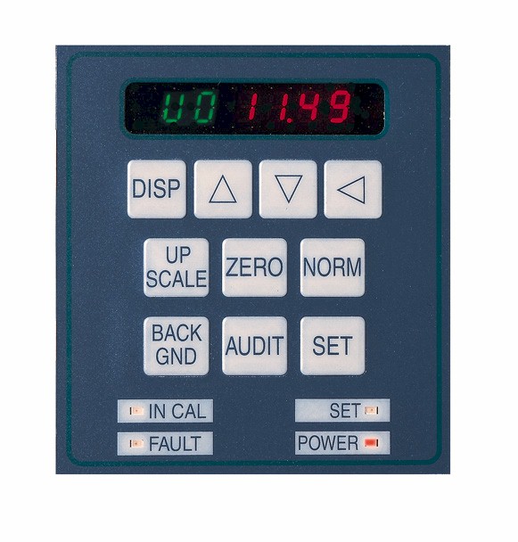
Optical Head Keyboard/Display
Uses a 10 button keypad & 6 digit readout to display and/or enter:
· Instantaneous Opacity
· Average Opacity
· Upscale Calibration
· Calibration Zero
· Dust Compensation
· Path Length Correction Factor
· Status Codes
· Diagnostic Data about the Analog Signals Inside the Optical Head (no need to open the Optical Head)
· Particulate Concentration Curves
· Optical Gains
· Alarm Settings

With optional Six Point I/O board, LightHawk® meets all PS-1 and ASTM D6216 requirements without a Remote Display Panel.
Calibration Kit
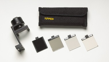
TThe calibration kit, standard with the LightHawk®, is used as an additional check of the unit's proper operation and calibration. The calibration fixture attaches to the front face of the optical head and has been preset to return the same amount of light as the retroreflector when the stack or duct is clear.

Ethernet Interface
The LightHawk® Enhanced Remote Panel now features 10/100 Based Ethernet interface as standard equipment. This capability provides a multilevel password protected interface to TCP/IP networks such as LAN's or the Internet. Client side user interface access is via standard web browsers. Simultaneous Modbus TCP access to instrument parameters and emission data is also supported.
